Hardware Hacking: Automating a USB3 Switch

When I'm working from home, I like to feel comfortable on my regular battlestation. My work has to be done on a company machine, however. To keep the familiarity of my setup while on my work laptop, I decided to use a KVM Switch.
The KVM Switch has inputs for my monitor and my USB devices, and two outputs: one going to my personal rig and the other to my work laptop dock. With the press of a button, I can toggle which PC everything is connected to.
The Problem
As my setup has grown, this has become a problem. With a total of 8 USB devices on a single hub feeding into the KVM, I've started to see many intermittent device issues which apparently haven't been seen by other users, at least as far as Google can tell. The issues seemed to appear as I added more devices, and even effected devices which were fine beforehand. I came to the honestly quite obvious conclusion that the large number of devices connected to a single USB2 hub were causing some sort of hardware-level communication issues.
Now, the KVM Switch I have is quite expensive. I can thank 4k@60Hz support for that. I could have bought a new hub with USB3 and 4k@60Hz, but that's more money spent and my old KVM wasted. I could have just bought a USB3 Switch and left it at that, but you can guess I had no desire to hit TWO BUTTONS to switch machines.
I'm an engineer. I could solve this easily.
The Plan
The first step was to actually pick up a USB3 Switch. Essentially a KVM Switch, but for USB3 devices. I realized I could use an Arduino to automate the USB3 switching, provided I had ways to:
- Detect the active PC on the KVM Switch
- Detect the active PC on the USB3 Switch
- Toggle the state of the USB3 Switch
The KVM Switch was about 10x the price of the USB3 Switch, so I decided not to tamper with it. Instead, I opted to use a photoresistor, which would change it's resistance based on ambient lighting, on the PC 1 indicator light. This allowed me to detect the state of the light, thus achieving #1.
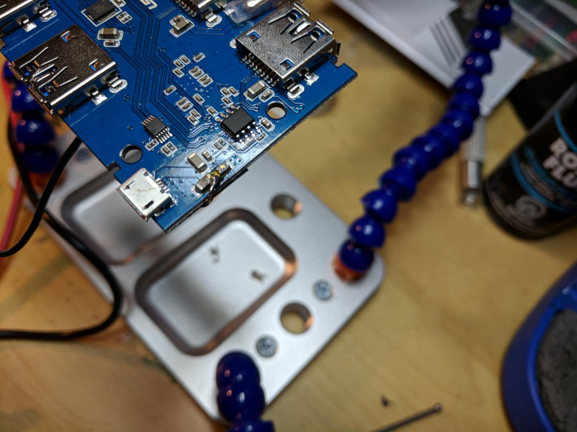
For #2 and #3, I decided to reverse engineer the USB3 Switch. First, I found a 5V rail on the board. This, along with the ground rails connected to every USB port, allowed me to power my Arduino Micro on the same circuit as the USB3 Switch.
Next, I did some digging into the actual circuitry. Starting simple, I found that the indicator lights were simple LEDs. 5V is sent to the light corresponding with the active PC, 0V to the other. I added some stems to anode of each LED on the underside of the PCB; checking the voltage on these would eventually achieve #2.
The final piece of the puzzle was to figure out how to toggle the USB3 Switch. A little bit more digging, and I found out it was using a simple ground switch: short the lead to ground momentarily to signal a toggle to the chip. I fussed around with my multimeter to make sure there was no resistance between the toggle's ground and the ambient ground, as it could be bad to do a direct short if the chip was expecting some resistance. As it turned out, however, a direct short was perfect, which meant I could achieve #3.
Implementation
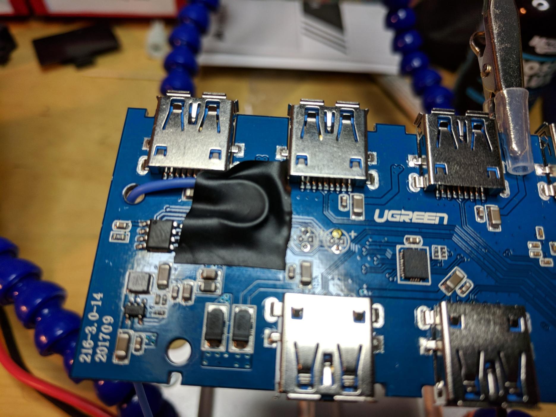
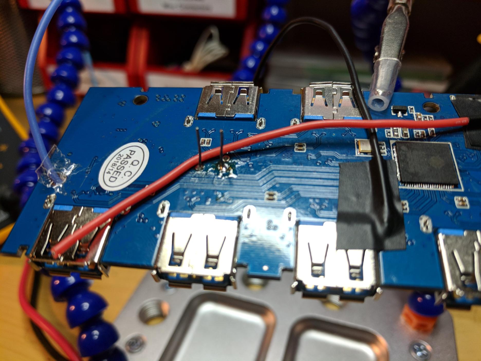
To start, I soldered a lead to the 5V rail.
Next, I soldered a black wire to ground, a red wire to my 5V lead, a blue wire to the toggle's anode, and a stem to the anode of each LED.
With these things ready to be connected and tested, it was time to write the code.
By momentarily setting a pin to OUTPUT, keeping it as INPUT otherwise, I could cause the Arduino to simulate a ground short to the pin. I used pin 6 for this and eventually connected the blue wire to it:
#define BUTTON_PIN 6

void toggle_pc() {
  digitalWrite(BUTTON_PIN, LOW);
  pinMode(BUTTON_PIN, OUTPUT);
  delay(500);
  pinMode(BUTTON_PIN, INPUT);
  delay(2000);
}

void setup() { // this runs at startup
  pinMode(BUTTON_PIN, INPUT);
}
I was careful to add generous delays in anticipation of misreading state when in the middle of a toggle. I'm not sure if I need this, but there's no reason to remove it.
Following this, I began the active PC detection logic using the analog pins and analogRead(). This function returns a value between 0 and 1023, where 5V is 1023 and 0V is 0.
Keep in mind that it doesn't actually operate at a flat 5V. The voltage will change depending on a number of factors. A value of
1023represents a voltage equal to that which is powering the Arduino, and the value scales linearly between 0 and1023. In addition, the analog pins are connected in a voltage divider in order to actually read accurate results. I'll cover this later.
With some testing, I found that there can be tiny fluctuations in the results. I made a helper function to average multiple reads. I don't think it's completely necessary, but figured it may prevent edge cases, and it was super simple to write. Because the indicator LEDs operate at the same voltage as the entire system, checking for close to 1023 was sufficient. For the photoresistor, however, tests showed that it only read around 800 when the light was on and 90 when it was off. I decided on 500 as a line in the sand:
#define PC_INDICATOR_1 A0
#define PC_INDICATOR_2 A1
#define PC_INDICATOR_EXT A2

bool indicator_activated(int pin, int thresh = 1015) {
  int sum = 0;
  for (int i = 0; i < 5; i++) {
    sum += analogRead(pin);
    delay(10);
  }
  return ((sum / 5) > thresh);
}

int get_active_pc_local() {
  if (indicator_activated(PC_INDICATOR_1)) return 1;
  else if (indicator_activated(PC_INDICATOR_2)) return 2;
  else return -1;
}

int get_active_pc_remote() {
  return (indicator_activated(PC_INDICATOR_EXT, 500)) ? 1 : 2;
}
And, finally, it was time to tie the logic together:
void loop() {
  int local = get_active_pc_local();
  if (local == -1) // shouldn't happen, but avoid spam toggling
    return;
  if (local != get_active_pc_remote())
    toggle_pc();
}
Breadboarding
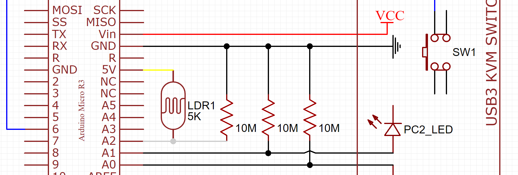
With the USB3 Switch ready to be connected and the code ready, it was time to test! The circuit was connected using a breadboard and a metric assload of jumper wires and alligator clips. I didn't think to take a picture, but this is a terribly drawn diagram:
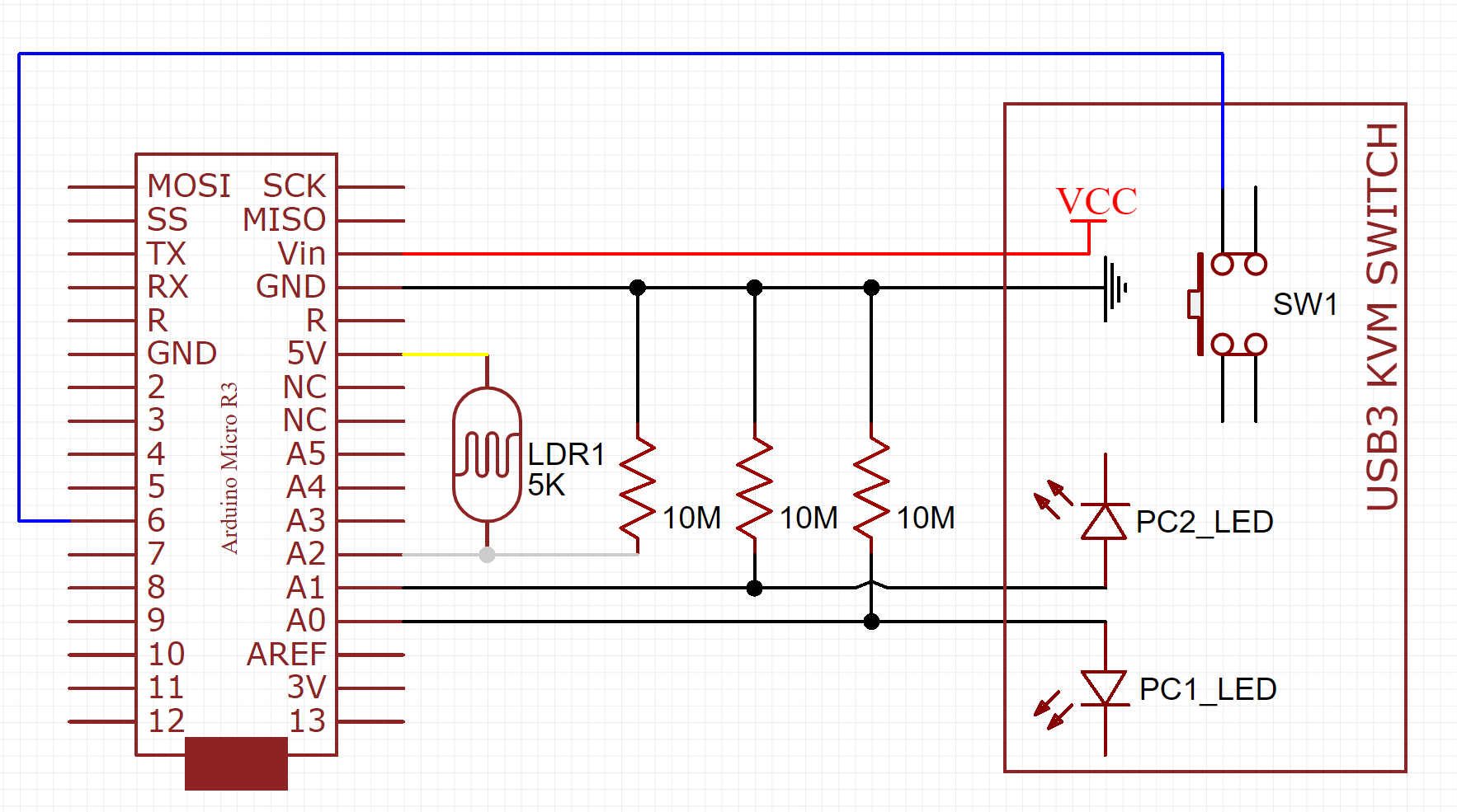
Notice the 10M resistors between each of the analog pins and ground. This creates what is called a voltage divider. Essentially, a voltage divider creates an output voltage that is the result of distributing its input voltage across some component(s). In this case, having a 10M resistor to ground creates a point-of-reference voltage for each analog pin. I'm not an electrical engineer, so I don't know the proper way to layman-ify this explanation, but take my word for it (because I took some random forum post's word for it, and it worked!).
I did have to work out some kinks along the way to arrive at the final code but, once I did, it worked!
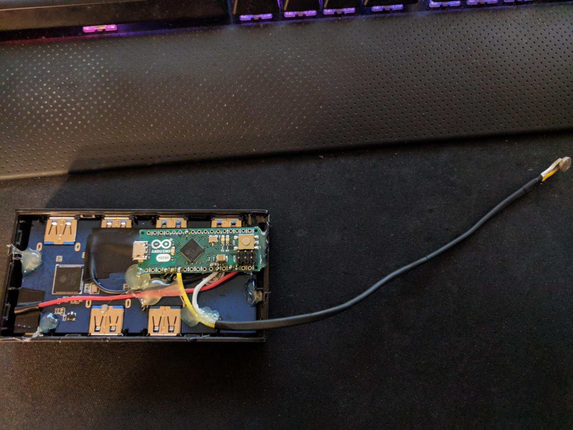
Consolidation
All that was left was to consolidate everything into a compact form. I used the stems from the indicator lights to hold the Arduino in place, through-holed all of my resistors, fed in the wire leads, and began soldering. Once I was done, I added a generous amount of hot glue to prevent any movement.
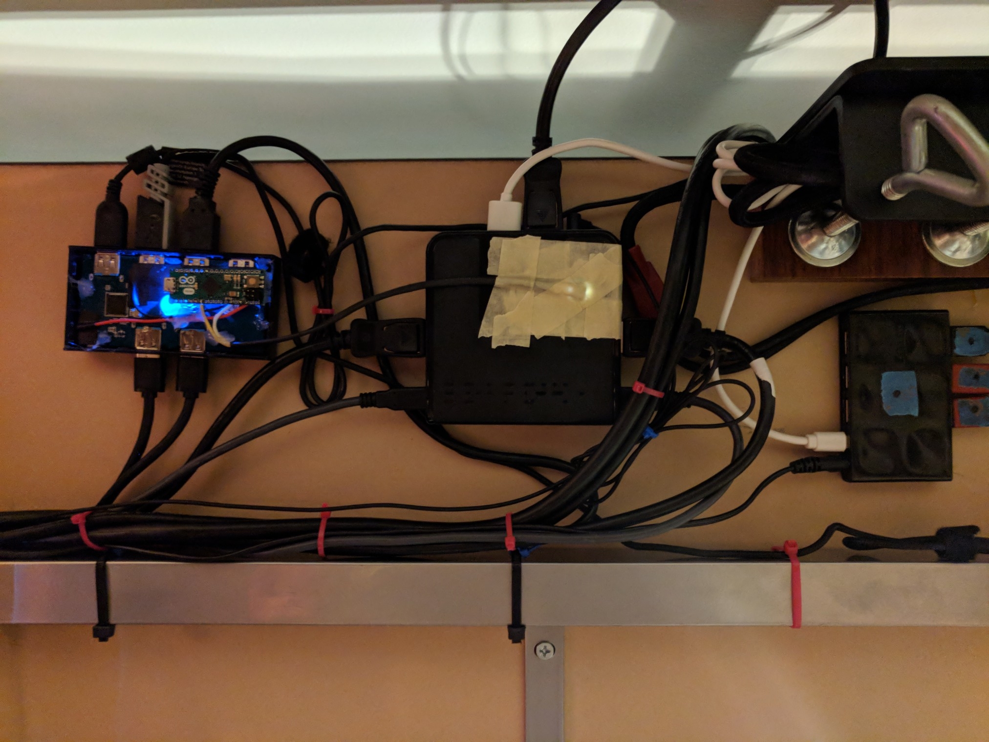
Hookup
Once the device was finished, I proceeded to mount it to my desk using velcro, tape the photoresistor to the KVM Switch's indicator light, connect all of the USB devices, and "neatly" route the cables to their destinations. You can see the old USB2 hub on the right, now blissfully managing half as many peripherals.
Results
I've only been testing this setup for a few hours now, but I've noticed a few of the obvious problems are gone. I'll continue to write code and play games to see if everything is behaving nominally. So far, I'm quite happy with the results of just 5 hours of work.
Thanks for reading! This was a fun project for me as I don't do a lot of electronics work these days, I hope you liked reading about it.